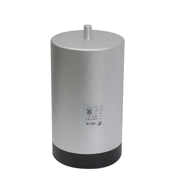
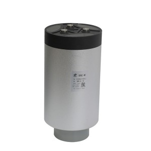
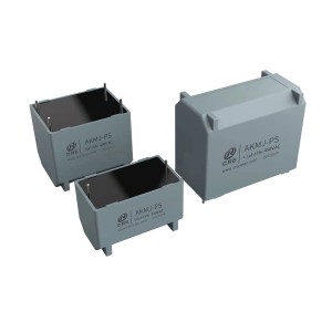
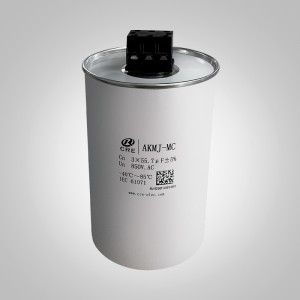
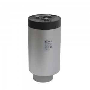
New AC filter capacitor for modern converter and UPS application
Technical data
| Operating temperature range | Max.Operating temperature.,Top,max: +85℃Upper category temperature:+70℃Lower category temperature:-40℃ | ||
| capacitance range | Single phase | 20UF~500μF | |
| three-phase |
3×40UF~3×200μF |
||
| Un/ Rated voltage Un |
330V.AC/50Hz~1140V.AC/50Hz |
||
| Cap.tol |
±5%(J) ; |
||
| Withstand voltage |
Vt-t |
2.15Un /10S |
|
|
Vt-c |
1000+2×Un V.AC 60S(min3000V.AC) |
||
| Over Voltage |
1.1Un(30% of on-load-dur.) |
||
|
1.15Un(30min/day) |
|||
|
1.2Un(5min/day) |
|||
|
1.3Un(1min/day) |
|||
|
1.5Un(100ms every time,1000times during the lifetime) |
|||
| Dissipation factor |
tgδ≤0.002 f=100Hz |
||
| tgδ0≤0.0002 | |||
| Insulation resistance | RS*C≥10000S(at20℃ 100V.DC) | ||
| Flame retardation |
UL94V-0 |
||
| Maximum aititude |
2000m |
||
| When the altitude is above 2000m to below 5000m, it is necessary to consider the use of reduced amount.(for each increase of 1000m, the voltage and current will be reduced by 10%)
|
|||
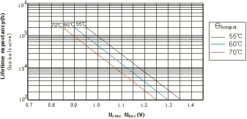
| Life expectancy |
100000h(Un; Θhotspot≤55 °C) |
||
| Reference standard |
IEC61071;IEC 60831; |
||
Feature
Our technology is dry design mostly, based on polypropylene dielectrics.
Applications range from DC filtering, AC filtering, snubbing, resonance to discharge and high energy storage.
Technology benefits
CRE film capacitor are available in a wide range of configurations and performance specifications, power film capacitors provide safer solutions than aluminum electrolytic, which have a limited voltage range and a high risk of leakage, and several other technologies that are physically unable to safely and effectively handle high voltage and high current at useful capacitance values.
Our experience technical team always support customers with specific solutions for their applications.
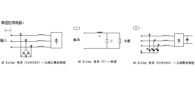
Typical circuit
Life expectancy
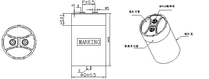
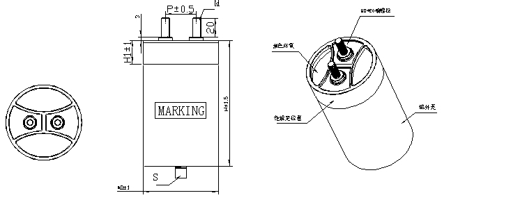
Outline drawing of single phase
|
ΦD(mm) |
P(mm) |
H1(mm) |
S |
F |
M |
|
76 |
32 |
20 |
M12×16 |
M6×10 |
M8×20 |
|
86 |
32 |
20 |
M12×16 |
M6×10 |
M8×20 |
|
96 |
45 |
20 |
M12×16 |
M6×10 |
M8×20 |
|
116 |
50 |
22 |
M12×16 |
M6×10 |
M8×20 |
|
136 |
50 |
30 |
M16×25 |
M6×10 |
M8×20 |
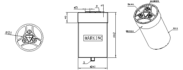
Outline drawing of three- phase
|
ΦD(mm) |
H1(mm) |
S |
F |
M |
D1 |
P |
|
116 |
40 |
M12×16 |
M6×10 |
M8×20 |
50 |
43.5 |
|
136 |
30 |
M16×25 |
M6×10 |
M8×20 |
60 |
52 |
| Voltage | Un=330V.AC Us=1200V | ||||||||||
| Cn (μF) | φD | H | ESL(nH) | dv/dt(V/μS) | Ip(KA) | Is(KA) | Irms(A)50℃ | ESR (mΩ) @1KHz | Rth(K/W) | P(mm) | weight(Kg) |
| 80 | 76 | 80 | 40 | 80 | 6.4 | 19.2 | 30 | 4 | 4.2 | 32 | 0.5 |
| 120 | 86 | 80 | 40 | 70 | 8.4 | 25.2 | 40 | 2.8 | 3.3 | 32 | 0.7 |
| 150 | 96 | 80 | 45 | 70 | 10.5 | 31.5 | 50 | 3.5 | 1.7 | 45 | 0.75 |
| 170 | 76 | 130 | 50 | 60 | 10.2 | 30.6 | 60 | 3.2 | 1.3 | 32 | 0.75 |
| 230 | 86 | 130 | 50 | 60 | 13.8 | 41.4 | 70 | 2.4 | 1.3 | 32 | 1.1 |
| 300 | 96 | 130 | 50 | 50 | 15.0 | 45.0 | 75 | 2.8 | 1.0 | 45 | 1.2 |
| 420 | 116 | 130 | 60 | 50 | 21.0 | 63.0 | 80 | 1.9 | 1.2 | 50 | 1.6 |
| Voltage | Un=450V.AC Us=1520V | ||||||||||
| Cn (μF) | φD | H | ESL(nH) | dv/dt(V/μS) | Ip(KA) | Is(KA) | Irms(A)50℃ | ESR (mΩ) @1KHz | Rth(K/W) | P(mm) | weight(Kg) |
| 50 | 76 | 80 | 40 | 90 | 4.5 | 13.5 | 30 | 4 | 4.2 | 32 | 0.5 |
| 65 | 86 | 80 | 50 | 80 | 5.2 | 15.6 | 40 | 2.8 | 3.3 | 32 | 0.7 |
| 80 | 96 | 80 | 45 | 80 | 6.4 | 19.2 | 50 | 3.5 | 1.7 | 45 | 0.75 |
| 100 | 76 | 130 | 50 | 70 | 7.0 | 21.0 | 60 | 3.2 | 1.3 | 32 | 0.75 |
| 130 | 86 | 130 | 45 | 60 | 7.8 | 23.4 | 70 | 2.4 | 1.3 | 32 | 1.1 |
| 160 | 96 | 130 | 50 | 50 | 8.0 | 24.0 | 75 | 2.8 | 1.0 | 45 | 1.2 |
| 250 | 116 | 130 | 60 | 50 | 12.5 | 37.5 | 80 | 1.9 | 1.2 | 50 | 1.6 |
| Voltage | Un=690V.AC Us=2100V | ||||||||||
| Cn (μF) | φD | H | ESL(nH) | dv/dt(V/μS) | Ip(KA) | Is(KA) | Irms(A)50℃ | ESR (mΩ) @1KHz | Rth(K/W) | P(mm) | weight(Kg) |
| 40 | 76 | 130 | 50 | 100 | 4.0 | 12.0 | 30 | 2.8 | 6.0 | 32 | 0.75 |
| 50 | 76 | 150 | 45 | 90 | 4.5 | 13.5 | 35 | 2.4 | 5.1 | 32 | 0.85 |
| 60 | 86 | 130 | 45 | 80 | 4.8 | 14.4 | 40 | 2.2 | 4.3 | 32 | 1.1 |
| 65 | 86 | 150 | 50 | 80 | 5.2 | 15.6 | 45 | 1.8 | 4.1 | 32 | 1.2 |
| 75 | 96 | 130 | 50 | 80 | 6.0 | 18.0 | 50 | 1.5 | 4.0 | 45 | 1.2 |
| 80 | 96 | 150 | 55 | 75 | 6.0 | 18.0 | 60 | 1.2 | 3.5 | 45 | 1.3 |
| 110 | 116 | 130 | 60 | 70 | 7.7 | 23.1 | 65 | 0.8 | 4.4 | 50 | 1.6 |
| 120 | 116 | 150 | 65 | 50 | 6.0 | 18.0 | 75 | 0.6 | 4.4 | 50 | 1.8 |
| Voltage | Un=850V.AC Us=2850V | ||||||||||
| Cn (μF) | φD | H | ESL(nH) | dv/dt(V/μS) | Ip(KA) | Is(KA) | Irms(A)50℃ | ESR (mΩ) @1KHz | Rth(K/W) | P(mm) | weight(Kg) |
| 25 | 76 | 130 | 50 | 110 | 2.8 | 8.3 | 35 | 1.5 | 8.2 | 32 | 0.75 |
| 30 | 76 | 150 | 60 | 100 | 3.0 | 9.0 | 40 | 1.2 | 7.8 | 32 | 0.85 |
| 32 | 86 | 130 | 45 | 100 | 3.2 | 9.6 | 50 | 1.15 | 5.2 | 32 | 1.1 |
| 45 | 86 | 150 | 50 | 90 | 4.1 | 12.2 | 50 | 1.05 | 5.7 | 32 | 1.2 |
| 40 | 96 | 130 | 50 | 90 | 3.6 | 10.8 | 50 | 1 | 6.0 | 45 | 1.2 |
| 60 | 96 | 150 | 60 | 85 | 5.1 | 15.3 | 60 | 0.9 | 4.6 | 45 | 1.3 |
| 60 | 116 | 130 | 60 | 80 | 4.8 | 14.4 | 65 | 0.85 | 4.2 | 50 | 1.6 |
| 90 | 116 | 150 | 65 | 75 | 6.8 | 20.3 | 75 | 0.8 | 3.3 | 50 | 1.8 |
| Cn (μF) | φD | H | ESL(nH) | dv/dt(V/μS) | Ip(KA) | Is(KA) | Irms(A) | ESR(mΩ) | Rth(K/W) | P(mm) | weight(Kg) | |
| Voltage | Un=400V.AC Us=1200V | |||||||||||
| Cn (μF) | φD | H | ESL(nH) | dv/dt(V/μS) | Ip(KA) | Is(KA) | Irms(A)50℃ | ESR (mΩ) @1KHz | Rth(K/W) | P(mm) | weight(Kg) | |
| 3× | 110 | 116 | 130 | 100 | 60 | 6.6 | 19.8 | 3×50 | 3×0.78 | 4.5 | 43.5 | 1.6 |
| 3× | 145 | 116 | 180 | 110 | 50 | 7.3 | 21.8 | 3×60 | 3×0.72 | 3.8 | 43.5 | 2.4 |
| 3× | 175 | 116 | 210 | 120 | 50 | 8.8 | 26.3 | 3×75 | 3×0.67 | 3.5 | 43.5 | 2.7 |
| 3× | 200 | 136 | 230 | 125 | 40 | 8.0 | 24.0 | 3×85 | 3×0.6 | 2.1 | 52 | 4.2 |
| Voltage | Un=500V.AC Us=1520V | |||||||||||
| Cn (μF) | φD | H | ESL(nH) | dv/dt(V/μS) | Ip(KA) | Is(KA) | Irms(A)50℃ | ESR (mΩ) @1KHz | Rth(K/W) | P(mm) | weight(Kg) | |
| 3× | 100 | 116 | 180 | 100 | 80 | 8.0 | 24.0 | 3×45 | 3×0.78 | 4.5 | 43.5 | 2.6 |
| 3× | 120 | 116 | 230 | 120 | 70 | 8.4 | 25.2 | 3×50 | 3×0.72 | 3.8 | 43.5 | 3 |
| 3× | 125 | 136 | 180 | 110 | 40 | 5.0 | 15.0 | 3×70 | 3×0.67 | 3.5 | 52 | 3.2 |
| 3× | 135 | 136 | 230 | 130 | 50 | 6.8 | 20.3 | 3×80 | 3×0.6 | 2.1 | 52 | 4.2 |
| Voltage | Un=690V.AC Us=2100V | |||||||||||
| Cn (μF) | φD | H | ESL(nH) | dv/dt(V/μS) | Ip(KA) | Is(KA) | Irms(A)50℃ | ESR (mΩ) @1KHz | Rth(K/W) | P(mm) | weight(Kg) | |
| 3× | 49 | 116 | 230 | 120 | 70 | 3.4 | 10.3 | 3×56 | 3×0.55 | 2.1 | 43.5 | 3 |
| 3× | 55.7 | 136 | 230 | 130 | 90 | 5.0 | 15.0 | 3×56 | 3×0.4 | 2.1 | 52 | 4.2 |
| Voltage | Un=850V.AC Us=2580V | |||||||||||
| Cn (μF) | φD | H | ESL(nH) | dv/dt(V/μS) | Ip(KA) | Is(KA) | Irms(A)50℃ | ESR (mΩ) @1KHz | Rth(K/W) | P(mm) | weight(Kg) | |
| 3× | 41.5 | 116 | 230 | 120 | 80 | 3.0 | 9.0 | 3×56 | 3×0.55 | 2.1 | 43.5 | 3 |
| 3× | 55.7 | 136 | 230 | 130 | 50 | 0.4 | 1.2 | 3×10⁴ | 3×0.45 | 1.8 | 52 | 4.2 |


